|
Stencil Module
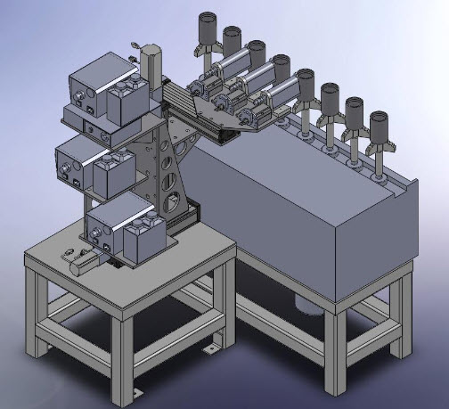
Shown here is a CAD prototype of a process machine intended to replace a slow, cumbersome, labor-intensive method for marking steel couplings with industry-specific information that complies with American Petroleum Institute (API) guidelines.
The isometric view shown here is taken directly from an assembly generated in SolidWorks.
Eight couplings are shown moving laterally along the production line, right to left.
Simultaneous rotation about their axes is driven by a clever countervailing chain within an existing vertical conveyor drive.
The module consists of a stage supporting three computer-driven spray heads which mark the couplings as they pass through the line.
The stage is motivated by three linear actuators, themselves driven by encoded motors.
The three printheads are individually adjustable to control text, and stenciling ink is supplied through the three tubes feeding each printhead. Control signals are routed through cabling stabilized with strain reliefs, and the stage is moved in all three axes by encoding gearmotors.
Module performance is dictated by barcodes read at the beginning and end of each series of couplings as the line continues to move. In finished form, the system is designed to process various diameters and lengths of steel couplings without interrupting production, processing 24,000 couplings per day in three continuous shifts.
|